Reading summary of UMTS Architecture. Circuit switching entities: Shared packet and circuit switching entities: Other areas that can be considered as part of the core network include:  The UMTS architecture comprises three parts (or domains):
1) Core network
2) Access network
3) User equipment. (Mobile device used to access UMTS services)
fig (a) High Level UMTS Architecture.
The user equipment has a radio interface to the access network. The access network manages access to the core network for all authorized users within its coverage area. The core network provides the central switching, transmission and service provisioning functions required to provide UMTS services.
The access network and core network communicate by the Iu interface. The access network and the user equipment communicate by the Uu interface.
User equipment has two components:
1) Mobile Equipment (ME). The ME is the terminal itself. It performs all radio transmission, reception and processing functions.
2) UMTS Subscriber Identity Module (USIM). A removeable card which uniquely identifies a UMTS user for authentication purposes, holds subscription-related information and provides
additional security features.
ACCESS Network:
The access network is known as the UMTS Terrestrial Radio Access Network (UTRAN) and performs the following functions:
1) Radio resource management
2) Call set up and handover
3) User access to the core network.
The UTRAN performs a similar role to the Base Station Subsystem (BSS) in GSM.
A UTRAN contains the following network entities:
1) Radio Network Subsystem (RNS)
The RNS is an abstract term that collectively defines the entities which manage the resources and transmission/reception for a particular set of cells.
Each RNS contains:
i) One Radio Network Controller (RNC).
ii) One or more Node Bs. Each Node B controls multiple UMTS cells.
2) Radio Network Controller (RNC)
The Radio Network Controller (RNC) controls the allocation and use of the radio resources in an RNS and performs most of the intelligent processing for the UTRAN. Each RNC controls one or more Node Bs.
RNC functions include:
i) Assigning and releasing radio channels. These may be locally controlled by the RNC or controlled from a neighbouring RNC
ii) Monitoring and maintaining connection quality
iii) Handover control
vi) Operations and maintenance:
- Configuration management
- Alarm and fault reporting
- Performance monitoring.
v) Macro diversity combining and splitting functions.
Most UTRAN functions are performed by the Radio Network Controller (RNC) entity.
3) Node B.
Node Bs are logical nodes that are responsible for radio transmission and reception between the User Equipment (UE) and UMTS cells.
1) One Node B serves multiple cells
2) Each Node B is controlled by one RNC
3) Node Bs can support Frequency Division Duplexing (FDD), Time Division Duplexing (TDD) or dual-mode operation.
Core Network:
The UMTS core network is responsible for:
1) Transmission and switching
2) User management
3) User services provisioning
4) Interworking with external networks.
The core network provides integrated support for packet and circuit switched traffic.
Most UMTS core networks are likely to evolve from an existing network infrastructure (GSM, PDN, N-ISDN, B-ISDN).
Services supported by the UMTS core network include: 
1) Voice
2) Universal messaging (integrated email, voicemail, SMS)
3) Video
4) Wireless internet access
5) File transfer
Interworking is supported to:
1) PSTN
2) GSM
3) N-ISDN
4) IP
fig(b): UMTS Reference model
The core network is logically divided into a circuit switching domain and a packet switching domain. The network entities are grouped into functional areas accordingly:
1) Entities to support packet-switched services
2) Entities to support circuit-switched services
3) Entities common to packet and circuit-switched services.
Packet switching entities:
1) Serving GPRS Support Node (3G-SGSN)
2) Gateway GPRS Support Node (3G-GGSN)
3) Domain Name Server (DNS)
4) Dynamic Host Configuration Protocol (DHCP) server
5) Firewall
6) Packet charging gateway.
1) Mobile Switching Center (3G-MSC)
2) Gateway MSC (GMSC)
3) Visitor Location Register (VLR).
1) Home Location Register (HLR)
2) Authentication Center (AuC)
3) Equipment Identity Register (EIR).
Separation of the circuit switching and packet switching domains is also achieved by separate logical interfaces between the core network and the UTRAN:
1) Network management systems (such as billing and provisioning, and service management)
2) Operations and Maintenance Center (OMC). 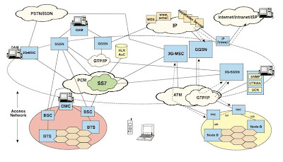
Overview of soft handover in UMTS (unlike of GSM):
Macro diversity refers to the capability of a UMTS UE to receive signals from more than one cell and vice versa - multiple cells can receive the signal from a UE. The cells can be controlled by different Node Bs.
A UE can be connected simultaneously to two or more cells, providing a multi-path communication channel. User data is split and carried over several channels.
Macro diversity has two advantages:
1) Sending the data across multiple channels reduces the impact of interference in any one path, providing improved overall connection quality
2) It allows seamless handover of the UE between currently connected cells (“soft” handover). In soft handover the UE always keeps at least one active connection to one of the cells, so
the radio path does not have to be dropped and reconnected (as is required in GSM).
The RNC manages the data splitting/combining and handover function across the multiple paths.
The RNC performs a similar function to the Base Station Controller (BSC) in GSM networks, but has more intelligence.
Wednesday, May 6, 2009
UMTS Architecture
Subscribe to:
Post Comments (Atom)
No comments:
Post a Comment